

Campus Architecture Table of Contents
The modern campus network is the essential connectivity fabric for today's enterprises, extending beyond the traditional office building to encompass branch locations and edge environments. Its fundamental role is to reliably and securely connect employees, facilitate access to critical applications from any location, enable seamless collaboration, and support an ever-increasing number of diverse devices, including the Internet of Things (IoT).
However, the demands placed upon the campus network have evolved significantly. It's no longer sufficient to provide basic connectivity; the network must now actively support digital transformation initiatives, requiring unprecedented levels of agility, scalability, and resilience. This evolution is driven by significant shifts in how businesses operate, including the rise of hybrid work models, widespread adoption of cloud services, and the proliferation of varied endpoint types connecting to the network.
This increasing complexity underscores the transition of the campus network from mere infrastructure to a strategic asset. Modern business operations are deeply intertwined with digital tools, cloud-based applications, and collaborative platforms. The effectiveness, reliability, and security of these essential tools are directly dependent on the performance and robustness of the underlying network infrastructure.
Consequently, a meticulously designed campus network is not simply an IT operational cost but a critical enabler of core business objectives, impacting productivity, fostering innovation, and shaping the overall user experience. Decisions made regarding network architecture, therefore, carry direct strategic implications for an organization's agility, competitiveness, and ability to adapt to future demands.
Core Principles: The Hierarchical Model
A foundational principle in designing reliable and scalable networks is the hierarchical network model, an industry-standard approach widely adopted for its proven benefits. This model logically divides the network into distinct layers, typically three: the Access, Distribution, and Core layers. Each layer fulfills specific functions, contributing to a structured, manageable, and predictable network environment.
Access Layer: This is the network edge where end-user devices (computers, laptops, IP phones, printers), IoT devices, and wireless access points connect to the network. Its primary functions include providing Layer 2 switched connectivity, ensuring port security, delivering Power over Ethernet (PoE) to connected devices, implementing Quality of Service (QoS) marking, and handling initial traffic entry.
Distribution Layer: Positioned between the access and core layers, the distribution layer acts as an aggregation point for traffic from multiple access layer switches. It serves as a critical control boundary, enforcing network policies through Access Control Lists (ACLs) and QoS mechanisms. This layer typically handles inter-VLAN routing, defines Layer 2/Layer-3 boundaries, aggregates wiring closets, and provides redundancy to the access layer. It isolates network problems and prevents issues in the access layer from propagating further up the hierarchy.
Core Layer: Often referred to as the network backbone, the core layer's sole purpose is to provide high-speed, highly reliable transport across the campus network. It interconnects the various distribution layer blocks, and potentially connects to the data center or the WAN edge. The core should be optimized for speed and availability, avoiding complex, CPU-intensive packet manipulations like granular policy enforcement or QoS classification, which are handled at lower layers.
The inherent structure of the hierarchical model facilitates network scalability and manageability. By assigning distinct roles to each layer, changes or expansions within one layer, such as adding new access switches to accommodate user growth, can be implemented with minimal impact on the other layers. The aggregation points at the distribution and core layers also provide fault isolation; an issue within one access-distribution block is contained and less likely to affect the entire network. This modularity, often conceptualized as "building blocks," allows the network to grow predictably and efficiently as organizational needs evolve.
The Collapsed Core Variation
While the three-tier model provides maximum scalability and segmentation, it's not always the most practical or cost-effective solution, especially for smaller organizations. A common variation is the collapsed core design, where the functions of the distribution and core layers are merged onto a single tier of switches.This two-tier architecture is suitable for smaller campuses (e.g., serving fewer than 1000-1500 users) or environments where extensive future growth is not anticipated. By eliminating the need for a dedicated set of core switches, the collapsed core design significantly reduces hardware costs and simplifies the physical topology.
Despite the consolidation, the fundamental principles of the core layer—high speed, reliability, and availability—remain critical in a collapsed core design. The switches performing the combined roles must provide robust, high-speed interconnectivity between the different access-distribution blocks they serve. Redundancy between these collapsed core/distribution switches is paramount, often achieved through full meshing or high-availability stacking/clustering technologies.
The collapsed core represents a pragmatic trade-off. While a dedicated three-tier design offers the highest degree of scalability and fault domain isolation, it comes at a higher cost and complexity due to the additional hardware layer. For smaller networks, the benefits of a separate core might not justify these costs. The collapsed core provides a balance, simplifying the network and reducing expenses while retaining many hierarchical benefits. However, it does create a potentially larger failure domain compared to a three-tier design and might present limitations if the network experiences unexpectedly rapid or large-scale growth. The decision between a three-tier and collapsed core design hinges on carefully evaluating current requirements, budget constraints, and realistic projections for future expansion.
Designing for Scalability
Building a campus network that can gracefully accommodate future demands is paramount. Scalability ensures the network can handle growth in the number of users, the explosion of connected devices (particularly IoT), and increasing bandwidth requirements without performance degradation or requiring costly, disruptive overhauls. Effective scalability planning involves several key strategies:
Modular Design: Structure the network using repeatable "building blocks," typically consisting of access and distribution layers. This modularity allows for easier expansion by simply adding new blocks as needed without significantly impacting the existing infrastructure.
Hierarchical Addressing and Routing: Implement a logical IP addressing scheme that aligns with the network hierarchy. Utilize route summarization at the distribution layer to minimize the propagation of routing updates into the core. This limits the impact of changes in the access layer on the core network's stability. Employ scalable interior gateway protocols (IGPs), such as OSPF or EIGRP, that can handle large and complex topologies efficiently.
High-Capacity Infrastructure: Select network hardware with sufficient capacity for anticipated growth. This includes switches with adequate backplane performance, port density (including high-density options like chassis-based or stackable switches), and high-speed uplinks (10Gbps, 40Gbps, 100Gbps). Increasingly important is the support for Multi-Gigabit Ethernet (2.5/5/10Gbps) at the access layer to support high-performance devices like Wi-Fi 6/6E access points.
Robust Physical Infrastructure: Plan beyond the active equipment. Ensure adequate physical space in wiring closets and the data center for future expansion. Install high-quality, future-proof cabling (e.g., Category 6A is recommended to support 10Gbps and higher PoE levels required by future devices like Wi-Fi 6E APs). Provide sufficient and reliable power (including UPS and potentially generator backup) and cooling to support increased equipment density.
Designing for scalability is fundamentally a proactive endeavor. Network demands, driven by user growth, device proliferation, and new applications, consistently trend upwards. Attempting to retrofit capacity or fundamentally change the architecture of a network not designed for growth is often highly disruptive, complex, and expensive. Early design decisions regarding cabling infrastructure, switch capacity, and features, and the adoption of a modular architecture have long-term consequences for the network's ability to adapt. Therefore, scalability should be a primary consideration from the project's inception, looking beyond immediate requirements to anticipate future needs.
Building Resilient Architectures
Network resilience refers to the network's ability to maintain acceptable service levels during failures—whether component failures, link outages, or unexpected load conditions—and to recover quickly from disruptions. It's distinct from, but related to, redundancy (the duplication of components to eliminate single points of failure) and backups (copies of data or configurations). Achieving a resilient campus network requires a multi-faceted approach encompassing hardware, topology, protocols, and automation:
Platform Redundancy: Utilize hardware designed for high availability, especially in critical distribution and core layers. This includes chassis-based switches with redundant supervisor engines, power supplies, and fans. Hot-swappable components allow for replacement without system shutdown.
Topological Redundancy: Avoid single points of failure in the physical layout. Deploy core and distribution switches in redundant pairs. Ensure access layer switches have dual uplinks to separate distribution switches. Utilize physically diverse paths for critical fiber links where possible to protect against cable cuts.
Link Redundancy: Employ Link Aggregation (LAG) using protocols like LACP to bundle multiple physical links into a single logical connection. This increases available bandwidth and provides redundancy; if one link in the bundle fails, traffic continues over the remaining links.
Device Redundancy and Failover
Stacking/Clustering: Technologies like Cisco StackWise, Aruba Virtual Switching Framework (VSF), Aruba Virtual Switching Extension (VSX), and Juniper Virtual Chassis allow multiple physical switches to operate as a single logical entity. This simplifies management and provides redundancy—if one member switch fails, the stack or cluster continues operating. Technologies like VSX also deliver control plane redundancy for added resilience.
Arista approaches this differently, avoiding traditional physical stacking in favor of cloud-scale principles. Arista’s architecture relies on high-availability Layer 2/Layer 3 designs with active-active uplinks, combined with CloudVision for unified management across the entire switch fabric. Rather than bonding switches into a physical stack, Arista provides centralized configuration, telemetry, and lifecycle management through CloudVision, enabling simplified operations and network-wide automation—without introducing stack-specific failure domains or scaling limitations. This model is inherently more flexible and aligns with the operational principles used in modern data center networks.
Multi-Chassis Link Aggregation (MLAG/MC-LAG): This architecture allows a downstream device—such as an access switch or server—to connect to two upstream switches using a single Link Aggregation Group (LAG). The upstream switches work together to present themselves as a single logical switch, enabling active-active traffic forwarding, load balancing, and rapid failover without relying on Spanning Tree Protocol (STP) to block links.
Vendor implementations include Cisco Virtual PortChannel (vPC) and StackWise Virtual, Aruba VSX, and Juniper MC-LAG. Arista implements this capability through Arista MLAG, a simple, scalable design that decouples the control planes of the two upstream switches while still ensuring consistent data plane behavior. Arista MLAG avoids centralized control dependencies and uses open, standards-based protocols combined with independent switch operation—resulting in higher availability and easier troubleshooting. Paired with CloudVision, Arista MLAG deployments gain enhanced visibility, configuration consistency, and proactive telemetry without sacrificing the operational simplicity that MLAG is designed to provide.
First Hop Redundancy Protocols (FHRPs): Protocols like HSRP (Cisco proprietary), VRRP (open standard), and GLBP (Cisco proprietary) enable multiple routers to provide a redundant default gateway for devices in Layer 2 access networks. If the active gateway fails, a standby device seamlessly takes over the virtual IP and MAC address, ensuring uninterrupted client connectivity. Arista supports VRRP as its standard for gateway redundancy, often deployed alongside Active-Active Leaf designs and MLAG for consistent Layer 3 availability without the complexity of traditional FHRP tuning. Combined with EVPN and CloudVision, Arista delivers highly resilient gateway services with enhanced visibility and automation, simplifying failover management in modern campus networks.
Control Plane Resiliency: Dynamic routing protocols like OSPF and EIGRP (Cisco proprietary) provide fast convergence after topology changes, especially when paired with route summarization to reduce routing update scope. Features such as Graceful Restart, Nonstop Forwarding (NSF), and Nonstop Routing (NSR) help maintain data plane forwarding during control plane disruptions. Arista enhances control plane resiliency using BGP with Graceful Restart and OSPF with Non-Stop Routing (NSR), along with stateful switch upgrades (SSU) and self-healing EOS architecture. Combined with Arista CloudVision, operators gain real-time visibility and rollback capabilities, ensuring predictable convergence and minimal disruption in campus environments.
Automation and Orchestration: Centralized management platforms like Cisco Catalyst Center, Aruba Central, and Juniper Mist streamline operations by enabling consistent configuration deployment, reducing human error. These tools also offer real-time monitoring and AIOps-driven analytics to detect anomalies, predict failures, and accelerate troubleshooting. Arista addresses this through CloudVision, its unified management and orchestration platform that provides a single point of control for the entire campus fabric. CloudVision offers network-wide automation, telemetry, and state streaming, enabling proactive operations and rapid remediation. Its integration with AIOps and macro- to micro-level visibility makes Arista particularly effective in supporting resilient, scalable campus networks.
True network resilience extends beyond simply having duplicate hardware. While redundancy is crucial for eliminating single points of failure, failures can still occur due to software issues, configuration errors, or larger-scale events. Resilience emphasizes the system's ability to continue functioning during such events and to recover rapidly. This necessitates intelligent design choices, including fast failover mechanisms like MLAG and tuned FHRPs or routing protocols, ensuring control plane stability through techniques like summarization, and potentially incorporating geographic diversity for critical services.
Furthermore, modern automation and AIOps capabilities enhance resilience by enabling faster detection, diagnosis, and remediation of issues, often before users are impacted. Thus, achieving resilience is a holistic endeavor combining robust hardware, smart topology and protocol design, and advanced operational practices.
Table 1: Key Resilience Technologies in Campus Networks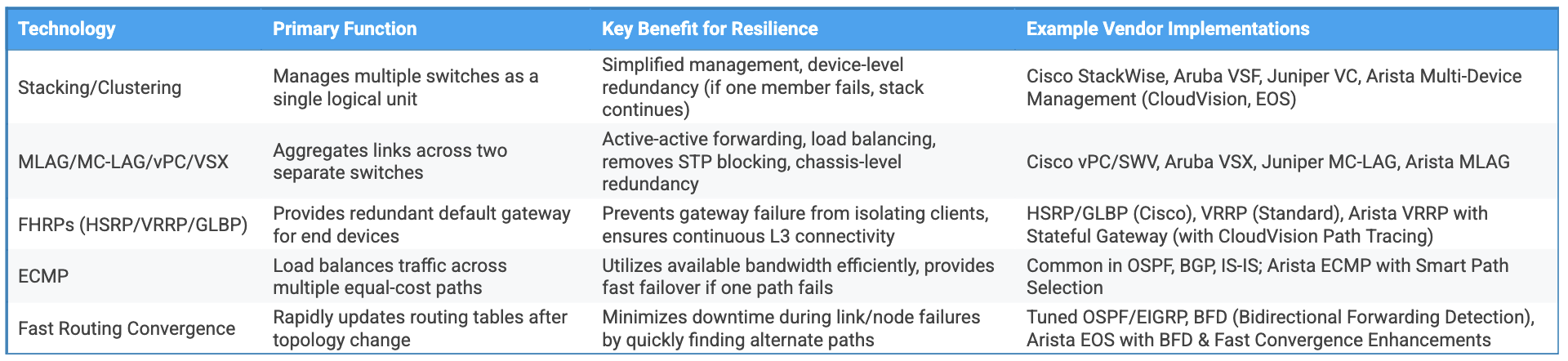
Modern Trends: Spine-Leaf in the Campus?
Originally developed for data centers, the spine-leaf architecture is increasingly influencing modern campus designs—often adopted and referred to as a “campus fabric.” In data centers, this two-tier model (leaf switches connecting to spine switches, with all endpoints just one hop apart) supports high-bandwidth, low-latency, and scalable east-west traffic using Equal-Cost Multi-Path (ECMP) routing.
When tailored for campus use, this architecture can offer several compelling benefits:
- Simplified Topology: Replaces the traditional three-tier (access–distribution–core) model with a flatter, more scalable two-tier structure.
- High Availability and Performance: ECMP and resilient uplinks across multiple spines provide built-in load balancing and fast failover.
- Improved Automation & Segmentation: Integration with overlay technologies like EVPN-VXLAN enables policy-driven automation and granular segmentation across the network.
However, campus networks differ fundamentally from data centers in several key ways:
- Traffic Patterns: Campuses are typically more north-south (client-to-core/cloud) than east-west.
- Device and Service Diversity: Endpoints include laptops, phones, PoE-powered IoT sensors, and Wi-Fi access points, all requiring features like voice VLANs, dynamic 802.1X, and per-port policy enforcement.
- Distributed Physical Topologies: Campus environments often span multiple buildings and floors, making cabling design and optical reach more complex than the structured cabling of data centers.
Arista’s Cognitive Campus approach bridges this gap by combining the agility of spine-leaf with the operational and feature set demands of a true enterprise campus. Arista enables EVPN-VXLAN campus fabrics with full PoE, advanced QoS, macro/microsegmentation, and context-aware policy enforcement at the edge. With CloudVision, Arista delivers centralized automation, telemetry, and compliance enforcement that adapts the principles of data center networking for a distributed access environment.
While the traditional hierarchical model (access–distribution–core) remains common, campus fabric designs based on spine-leaf and overlay principles are rapidly gaining traction—especially in large, dynamic enterprise environments seeking to mirror data center-like agility, segmentation, and automation without sacrificing the operational features needed for end-user connectivity.
Conclusion
Designing a modern campus network architecture demands a strategic approach grounded in the core principles of hierarchy, scalability, and resilience. The traditional three-tier model provides a proven foundation, while variations like the collapsed core offer cost-effective alternatives for smaller deployments. Emerging campus fabric designs based on spine-leaf principles present opportunities for enhanced performance and automation, particularly in larger environments, but require careful adaptation to unique campus needs.
Ultimately, the optimal design depends on a thorough assessment of the organization's specific requirements, current infrastructure, budget constraints, and future growth projections. Regardless of the chosen architecture, prioritizing scalability from the outset and embedding resilience through redundant components, intelligent topology, and robust protocols is essential. A well-architected campus network is no longer just a utility; it is a critical enabler of productivity, collaboration, and digital transformation in the modern enterprise.