

Table of Contents
The Foundation of Campus Connectivity
Local Area Network (LAN) switching forms the bedrock of connectivity within any enterprise campus. Utilizing network switches, this technology enables devices within a building or campus to communicate efficiently and reliably. While fundamental, modern LAN switching extends far beyond simply connecting devices; it involves intelligent data forwarding, crucial network segmentation, support for diverse endpoint needs like Power over Ethernet (PoE), and increasingly sophisticated operational management.
The performance and stability of the campus network rely heavily on the proper design and operation of the switching infrastructure. This involves understanding core Layer 2 concepts, implementing robust strategies for managing the lifecycle of switch software, and developing effective methodologies for troubleshooting inevitable issues. This section delves into these critical aspects of LAN switching and operations, providing insights for maintaining a high-performing and reliable campus network. The role of switching continually evolves, driven by demands for higher speeds to support technologies like Wi-Fi 6E, increased power delivery for a myriad of devices 1, advanced security through segmentation, and tighter integration with network automation frameworks. Therefore, mastering the foundational principles and the evolving capabilities of LAN switching is essential for effective campus network management.
LAN Switching Fundamentals
At its core, LAN switching operates at Layer 2 (the Data Link Layer) of the OSI model, primarily concerned with forwarding data frames based on hardware addresses within a local network segment.
Key concepts include:
MAC Address Learning: Switches build a dynamic table, often called a MAC address table or CAM table, by inspecting the source MAC address of incoming Ethernet frames. The switch associates the source MAC address with the port on which the frame was received. This learning process allows the switch to forward future frames destined for that MAC address intelligently.
Frame Forwarding/Filtering: When a frame arrives, the switch examines the destination MAC address. It consults its MAC address table. If an entry exists for the destination MAC, the switch forwards the frame only out the associated port, filtering it from other ports. This targeted forwarding is a major efficiency improvement over older hub technology.
Flooding: If the destination MAC address is not found in the MAC address table (an unknown unicast), or if the frame is a broadcast (destination MAC FFFF.FFFF.FFFF) or multicast frame, the switch floods the frame. Flooding means sending the frame out all ports except the port on which it arrived, but only within the boundaries of the frame's VLAN. While necessary for discovery protocols (like ARP) and initial communication, excessive flooding can consume bandwidth.
Collision Domains: Unlike hubs which operate as shared electrical buses creating a single large collision domain, switches create a separate collision domain for each port. This means devices connected to different switch ports can transmit simultaneously without causing collisions, enabling full-duplex communication and significantly improving network performance.
Broadcast Domains & VLANs: By default, a switched network forms a single broadcast domain, meaning a broadcast frame sent by one device is flooded to all other devices. As networks grow, broadcast traffic can become excessive and degrade performance. Virtual LANs (VLANs) solve this by logically segmenting a physical network into multiple isolated broadcast domains. Devices within the same VLAN can communicate directly at Layer 2, but traffic between different VLANs must be routed (typically at the distribution layer). VLANs are fundamental for managing traffic and providing basic segmentation in modern LANs. Trunk links are used to extend VLANs across multiple switches. These links carry traffic for multiple VLANs simultaneously, using the IEEE 802.1Q tagging standard to identify which VLAN each frame belongs to.
VLANs represent the primary Layer 2 mechanism for controlling broadcast traffic and implementing initial network segmentation. In any reasonably sized LAN, their use is essential for performance and security. By dividing the network into smaller broadcast domains, VLANs prevent broadcast storms that can cripple large flat networks and provide a basic security boundary by preventing direct Layer 2 communication between devices in different VLANs. The ability to span VLANs across multiple switches via 802.1Q trunking enables the creation of scalable, segmented network designs.
Ensuring Stability: Spanning Tree Protocol (STP)
Designing networks with redundant paths between switches is crucial for high availability. However, these redundant paths create the potential for Layer 2 loops. Ethernet frames lack a Time-to-Live (TTL) mechanism like IP packets, so broadcast frames caught in a loop will circulate indefinitely, rapidly consuming bandwidth and switch CPU resources, leading to a "broadcast storm" that can bring the network down.
The Spanning Tree Protocol (STP) is the mechanism designed to prevent these detrimental loops in Ethernet networks with redundant links. STP achieves this by logically disabling redundant paths, ensuring only one active path exists between any two points in the Layer 2 network at any given time.
Its basic operation involves:
Root Bridge Election: Switches exchange Bridge Protocol Data Units (BPDUs) to elect a single "root bridge" for the spanning tree domain (or per VLAN in some versions). The switch with the lowest Bridge ID (a combination of priority and MAC address) becomes the root.
Path Cost Calculation: Each switch calculates the lowest cost path back to the root bridge.
Port Role Determination: Based on path costs, switches designate ports as Root Ports (best path towards the root), Designated Ports (forwarding traffic onto a segment), or Blocking/Alternate Ports (logically blocked to prevent loops).
Common STP variants include:
Legacy STP (802.1D): The original standard, known for slow convergence times (30-50 seconds).
RSTP (Rapid Spanning Tree Protocol - 802.1w): Offers significantly faster convergence (typically sub-second or a few seconds) by optimizing the protocol mechanisms. This is the recommended standard for most networks.
MSTP (Multiple Spanning Tree Protocol - 802.1s): Allows grouping multiple VLANs into instances, running a separate spanning tree for each instance. This can improve load balancing in complex VLAN environments but adds configuration complexity.
Proper STP configuration is vital. A common mistake is allowing the network to automatically elect a root bridge, which can result in a suboptimal or underpowered switch becoming the root, leading to inefficient traffic paths. Manually configuring root bridge priorities, typically placing the primary root at the core or distribution layer, is a critical best practice.
While STP is indispensable for preventing loops in networks utilizing Layer 2 redundancy, its inherent mechanism of blocking links means that bandwidth on redundant paths goes unused during normal operation. Furthermore, the time it takes for STP to converge after a topology change (a link or switch failure/recovery) can cause temporary network outages, particularly with the older 802.1D standard.
Consequently, modern network designs often aim to minimize the scope and impact of STP. Technologies like switch stacking and Multi-Chassis Link Aggregation (MLAG) create loop-free logical topologies at the access and distribution layers, eliminating the need for STP to block uplinks between these layers. Similarly, extending Layer 3 routing closer to the network edge (routing at the distribution or even access layer) effectively eliminates Layer 2 loops in those segments.
Therefore, while STP remains a necessary component wherever Layer 2 redundancy exists, contemporary best practices focus on designing architectures that limit its domain and rely on faster, more efficient redundancy mechanisms like MLAG or Layer 3 ECMP.
Switch Software Upgrade Strategies
Keeping network switch software (firmware/OS) up-to-date is crucial for maintaining security, stability, and functionality. Upgrades deliver vital security patches, fix software bugs that could cause instability or unexpected behavior, and often introduce new features or performance enhancements. However, upgrading switch software often requires a reboot, leading to network downtime. Planning and executing upgrades carefully is essential to minimize disruption to business operations.
Best practices include:
Planning and Preparation:
Assessment: Inventory switches, document current firmware versions, and understand the network topology and dependencies.
Research: Thoroughly review vendor release notes for the target software version. Understand new features, bug fixes, known issues, hardware compatibility, and any potential intermediate upgrade steps required. Platforms like Arista, with a single binary across the entire product line drastically simplify this process.
Prioritization: Prioritize upgrades based on security vulnerability severity, bug fixes relevant to your environment, or critical feature needs.
Develop Plan: Create a detailed upgrade plan including:
Schedule: Define maintenance windows, considering business impact and user activity.
Backup: Back up current switch configurations before starting.
Rollback Procedure: Define clear steps to revert to the previous firmware version if the upgrade encounters critical issues. Utilize firmware partitions or snapshots if the platform supports them.
Communication: Notify stakeholders and end-users of planned maintenance and potential impacts.
Testing:
Lab Environment: Whenever possible, test the new firmware version and upgrade procedure in a non-production lab environment that mirrors your production setup
Pilot Group: Consider upgrading a small, non-critical segment of the network first to validate stability before wider deployment.
Execution Methods: The chosen method depends on the switch platform, network design (redundancy), and tolerance for downtime:
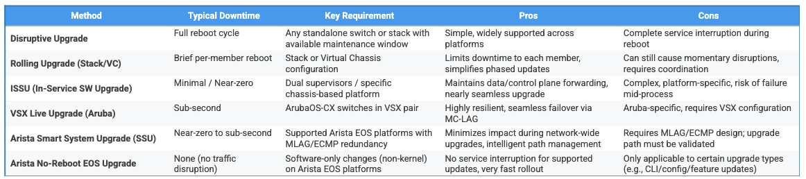
Disruptive Upgrade: The standard method involves uploading the new firmware and rebooting the switch. This causes a service interruption during the reboot cycle. Requires careful scheduling within approved maintenance windows.
Rolling Upgrades (Stacks/Virtual Chassis): In stacked or Virtual Chassis environments, members can often be upgraded sequentially. The stack master pushes the firmware to members, and reboots can be staggered (if supported by the specific feature, e.g., Aruba VSF Fast Software Upgrade) or managed to minimize disruption, relying on the inherent redundancy of the stack/VC. Traffic may experience brief interruptions as individual members reboot or during master failover.
High Availability (HA) Upgrades: Designed for minimal or zero downtime:
ISSU (In-Service Software Upgrade): Available on some platforms, particularly modular chassis switches with redundant supervisor engines (e.g., Cisco Nexus). ISSU aims to upgrade the software without impacting the control and data planes, allowing traffic forwarding to continue during the process. Specific procedures and limitations vary by vendor and platform; consult vendor documentation.
VSX Live Upgrade (ArubaOS-CX): Specifically for Aruba switches configured in a VSX pair. This orchestrated process upgrades one VSX peer while the other remains active, leveraging the MCLAG links and independent control planes to achieve sub-second failover and minimal traffic disruption.
Arista Smart System Upgrade (SSU): Arista’s approach to high availability upgrades is designed for cloud-scale and campus environments. SSU allows for staged software upgrades across devices in a network while maintaining service continuity. When combined with Arista’s MLAG (for distribution/access pairs) and control plane separation, the upgrade process ensures minimal traffic loss and maintains consistent forwarding behavior throughout the upgrade window.
Rollback Plan: Have a documented procedure to revert to the previous stable firmware version if the upgrade fails or introduces instability. This might involve booting from a secondary firmware partition or manually reloading the previous version.
Post-Upgrade Monitoring: After the upgrade, closely monitor switch performance (CPU, memory), interface status, logs, and network connectivity. Verify that the network is operating as expected and that the upgrade has resolved the intended issues or enabled new features.
Choosing a Switch Upgrade Strategy: Balancing Risk, Cost, and Continuity
The right switch upgrade method depends on how much downtime a business can tolerate and how critical the affected part of the network is. Disruptive upgrades (where the device reboots) are the simplest to perform but involve service interruption, potentially impacting productivity, operations, or revenue.
For more critical environments, high-availability upgrade options like Cisco’s ISSU, Aruba’s VSX Live Upgrade, and Arista’s Smart System Upgrade (SSU) offer a way to reduce or eliminate downtime. These approaches allow traffic to continue flowing while the software is upgraded. However, most of these methods (except Arista SSU in most cases) require additional investment in redundant hardware, such as dual supervisor modules or dual-switch configurations, and come with added design and operational complexity, which can be offset with proper network automation (e.g., Arista AVD).
Rolling upgrades in stacked switch environments present a middle ground. While they avoid taking the entire stack offline, they still involve brief interruptions as each unit is upgraded sequentially and requires careful coordination to minimize risk.
Ultimately, organizations must weigh the cost and complexity of high-availability upgrade capabilities against the business impact of downtime. In most enterprise environments, especially at the core and distribution layers, investing in HA features is justified to maintain continuous service and network resilience.
Table: Comparison of Switch Upgrade Methods
Troubleshooting Common LAN Issues
Despite careful design and maintenance, network issues inevitably arise. A systematic approach to troubleshooting is crucial for efficient problem resolution. A common methodology involves:
Identify the Problem: Clearly define the symptoms reported by users or monitoring systems.
Gather Information: Collect data using logs, user reports, and diagnostic tools.
Establish a Theory: Formulate a hypothesis about the probable cause based on the gathered information.
Test the Theory: Use specific tools and commands to confirm or refute the hypothesis.
Establish a Plan & Implement Solution: Develop and execute a plan to fix the issue.
Verify Full System Functionality: Confirm the problem is resolved and no new issues were introduced.
Document Findings: Record the problem, steps taken, and the solution for future reference.
Common LAN issues and troubleshooting tools/techniques include:
Connectivity Issues:
Physical Layer: Always check the basics first. Verify cable connections are secure, check link status lights on devices, and use switch commands like show interfaces status to confirm the port state (up/down, connected/notconnect). Examine interface counters (show interfaces) for physical errors like CRCs, input errors, or collisions (though collisions are rare on full-duplex switched ports). Cable testers can diagnose faulty wiring or termination issues.
VLAN Configuration: Incorrect VLAN assignment is a frequent cause of connectivity problems. Use show VLAN brief (Cisco) or equivalent to verify the port is assigned to the correct VLAN. On trunk links, use show interfaces trunk to ensure the necessary VLANs are allowed and check for native VLAN mismatches between connected switches.
IP Addressing/DHCP: On the end device, use ipconfig (Windows) or ifconfig (Linux/macOS) to check if it has obtained a valid IP address, subnet mask, and default gateway. If using DHCP, verify the DHCP server is reachable and operational. Check DHCP relay agent configurations on routers/L3 switches if the server is on a different subnet. Look for rogue DHCP servers using features like DHCP Snooping.
Basic Reachability (L3): The ping command is fundamental for testing IP connectivity between source and destination. It verifies reachability and measures round-trip time and packet loss. The traceroute (Linux/macOS) or tracert (Windows) command maps the Layer 3 path hop-by-hop towards the destination, showing the latency at each hop and helping identify where connectivity fails or high latency occurs.
ARP Resolution: If devices are on the same subnet but cannot communicate, check the Address Resolution Protocol (ARP) cache using the arp -a (Windows) or show arp (Cisco IOS) command to ensure correct IP-to-MAC address mapping.
Performance Issues:
Congestion/High Utilization: Monitor interface bandwidth utilization (show interfaces) to identify overloaded links or ports. Tools like NetFlow or packet analyzers (e.g., Wireshark, tcpdump) can provide deeper insight into traffic patterns and top talkers.
Duplex/Speed Mismatches: Ensure interface speed and duplex settings are correctly negotiated or manually configured consistently on both ends of a link. Mismatches can cause significant performance degradation and errors.41 Check using show interfaces.
Broadcast Storms: Often symptomatic of a Layer 2 loop. Look for extremely high broadcast/multicast packet counts on interfaces and high switch CPU utilization. Investigate STP status immediately.
Spanning Tree Protocol (STP) Issues:
Loops/Instability: Symptoms often include network-wide slowdowns, intermittent connectivity loss, and high switch CPU utilization. Use show spanning-tree detail to check for recent Topology Change Notifications (TCNs) and identify the source. Examine logs (show log) for flapping ports, which frequently trigger TCNs.
Incorrect Root Bridge: Verify the designated root bridge for each VLAN/instance using show spanning-tree root or similar commands. Ensure core or distribution switches have the lowest (best) priority values configured.
Unexpected Blocked Ports: Use show spanning-tree blockedports to identify ports STP has placed in a blocking state. Investigate why a needed path might be blocked. Common causes include misconfigurations like enabling PortFast on inter-switch links, BPDU Guard triggering on legitimate links, mixing incompatible STP types (e.g., PVST+ and MSTP) without proper configuration, or complex issues related to MSTP instance boundaries and pruned VLANs on trunks. Also, ensure STP root placement aligns with FHRP active router placement to avoid suboptimal traffic paths.
Effective LAN troubleshooting necessitates a layered approach. Problems can manifest at any level, from a disconnected cable (Layer 1) to an incorrect VLAN assignment (Layer 2) or a misconfigured IP address (Layer 3).
Tools are specific to layers: physical checks and interface counters address Layer 1/2, VLAN and STP commands diagnose Layer 2 issues, while ping and traceroute test Layer 3 connectivity. Starting diagnostics at the physical layer and systematically moving upwards through the OSI model ensures a thorough investigation and prevents premature conclusions based on incomplete data. Utilizing vendor-specific show commands (or their equivalents) is essential for gathering detailed status information from network devices.
Conclusion
A high-performing and reliable campus LAN hinges on a solid understanding of Layer 2 switching fundamentals, including MAC learning, VLANs, and the critical role of Spanning Tree Protocol. Beyond design, operational excellence is key. This involves implementing strategic, well-tested software upgrade procedures that minimize disruption, leveraging high-availability features where appropriate based on business needs. Furthermore, developing a methodical troubleshooting approach, utilizing the right diagnostic tools for each network layer, is essential for rapidly resolving issues and maintaining the integrity and availability of the campus network. Consistent attention to these operational aspects ensures the network can effectively support the organization's communication and application needs.